Electronics Design

What Electronics Design Covers

Electronics design covers everything from choosing the processor and key components to the schematic, the PCB layout, the power and battery system, and the prototype builds that prove the board works. At PDE, manufacturing, thermal, and EMC performance are design inputs from the first schematic, and the board is designed in the same team as the firmware that runs on it and the enclosure that holds it.

  • Architecture & Components

    Requirements, the processor, and the key parts, chosen before the schematic starts.

    • Requirements and power budget
    • Processor selection
    • Component selection
    • Multi-board architecture
    • BOM cost
  • Schematic & Layout

    Digital and analog circuits captured and laid out for manufacturing, heat, and EMC.

    • Altium Designer, OrCAD, PADs
    • Digital and analog design
    • Multi-layer stackups
    • EMC-aware layout
    • Test access
  • Power & Battery

    Power systems sized for how the product is actually used.

    • DC-DC and LDO regulators
    • Battery management
    • Charging and USB-C
    • Low-power design
    • Backup power
  • Prototypes & Production

    Boards built, brought up, and tested before they go to a contract manufacturer.

    • DFM/DFA
    • Prototype build management
    • Board bring-up
    • Pre-compliance testing
    • Design reviews
Prototype to Production

From Dev Kit to Custom PCB

PDE turns a dev-kit prototype into a custom circuit board by capturing the schematic, selecting production components, and laying out the PCB for manufacturing, thermal, and EMC performance. PDE firmware developers help choose the processor so it has the memory and peripherals the code needs, and DFM/DFA analysis runs alongside layout, so the first prototype run is close to what a contract manufacturer can build at volume.

  1. Pin down the requirements. What the board has to do, how it is powered, the space it has to fit, the target cost, and the certifications the product will need. These set the limits every later decision works within.
  2. Choose the processor and key parts. Firmware developers take part in processor selection, so the part has enough Flash, RAM, and peripherals. Choosing a processor without that input can mean throwing away boards later.
  3. Capture the schematic. Digital and analog circuits, DC-DC converters and power management, protection, and test access, captured in Altium Designer, OrCAD, or PADs.
  4. Lay out the board. Stackup, placement, and routing are set against manufacturing, thermal, and EMC targets.
  5. Build and bring up prototypes. PDE manages the prototype build, firmware is brought up on the first boards, and pre-compliance testing catches EMC and radio problems while they are still inexpensive to fix. Expect more than one round.

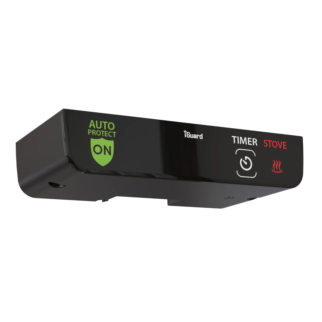
For the second-generation iGuard stove safety device, PDE designed three custom PCBs in Altium Designer: a control board built around an ARM Cortex-M33 processor, a display board with a capacitive touch interface, and a mmWave radar daughter board that mounts behind the faceplate and detects occupancy through the enclosure.
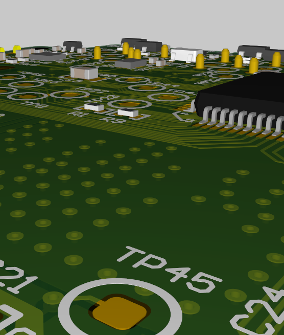
3D view of a PCB layout in Altium Designer showing surface-mount components and labelled test points
Electronics, Firmware & Mechanical Together

Boards Designed With Their Firmware and Enclosure

A circuit board sets limits for everything around it: the processor and pins the firmware gets, the outline and heat the enclosure has to work with, and the layout that decides EMC test results. When one team designs all three, those limits are settled in a design review instead of discovered at bring-up or in the test lab.

  • The processor: firmware developers help choose it, so it has the memory, peripherals, and low-power modes the code will need.
  • The board outline: the mechanical team designs the enclosure around the same outline while layout is under way, so connectors, displays, and buttons line up with their openings.
  • The antenna: the RF team sets keep-out areas and antenna placement before routing starts.
  • EMC: layout decisions are checked in PDE's own RF chamber with pre-compliance testing, before the product goes to a certification lab.

On the BlackTrax Beacon 2.0, PDE designed the electronics, enclosure, firmware, and interface for CAST and took the product through certification. The PCB layout and the enclosure were designed in parallel to keep the boards and housing aligned, and the firmware was written alongside the hardware it runs on. PDE has also delivered the electronics as part of full product development for the AGI Westeel Guardian grain-monitoring system, the InMotion Mobile Gateway in-vehicle router, and the Amerec K200i wireless steam control.

Obsolete Components

End-of-Life Parts and Board Redesigns

Find the closest replacement, then change only what it forces: anything from a drop-in substitute to a new processor with a revised layout. The scope depends on how closely the replacement matches the original part’s footprint, pinout, and electrical behaviour. PDE evaluates the candidates, revises the schematic, layout, and firmware as needed, and checks whether the change affects the product’s certification.

How much of the board has to change depends on the replacement:

  • Drop-in substitute: same footprint, pinout, and electrical behaviour. Usually a bill of materials change plus verification testing.
  • Different footprint or pinout: the circuit stays largely the same, but the layout is revised around the new part.
  • Functional replacement: a different microcontroller, power IC, or sensor. The schematic, the layout, and the firmware drivers and pin mapping all change.
  • Several parts at once: when multiple parts are going end-of-life, it is often worth folding in cost reduction or new features while the board is open.
  1. Assess the bill of materials. Identify the affected parts and any others nearing end-of-life, so one redesign covers them.
  2. Evaluate replacement candidates. Compare electrical behaviour, footprint, availability, and the firmware changes each candidate would need.
  3. Revise the schematic and layout. Change only what the replacement requires, or plan a broader refresh if one is warranted.
  4. Update the firmware. Drivers, peripheral configuration, and pin assignments are changed at the same time as the hardware.
  5. Verify and check certification. Test the revised board, then determine whether the change needs no filing, a permissive change, or new certification. See Compliance & Certification for how that decision is made.
A stack of populated multi-layer circuit boards
Power Design

Battery Life and Power Systems

Start from a power budget: what each circuit draws in each operating mode, and how long the device spends in each one. Battery life is set by average current, so sleep current and how quickly the device returns to sleep often matter more than peak draw. PDE designs the power supply, battery management, and charging circuits against that budget, and PDE firmware developers write the code that keeps the device asleep.

  • Sleep current: a device that sleeps most of the time spends most of its battery there. Leakage through pull-up resistors, voltage dividers, and always-on regulators adds up.
  • Duty cycle: how often the processor, sensors, and radio wake, and how long they stay awake, sets the average current.
  • Regulator choice: DC-DC converters and LDO regulators trade efficiency against quiescent current and noise. The right answer depends on the load in each operating mode, not just at full power.
  • The radio: transmitting is often the largest single load. Protocol, transmit power, and reporting interval are worked out with RF & Wireless.
  • Battery and charging: the cell, the charging circuit, protection, and how the device is charged in use all shape the power system.

The BlackTrax Beacon 2.0, a battery-powered belt pack worn by performers, runs on a low-power STM32L4 microcontroller with battery charging designed into the same board. The BlackTrax Mini Beacon runs for eight hours on its battery and charges in a shared dock that holds up to 20 units.

Our Standards

Boards Your Team Can Build On

PDE reviews every design against an internal checklist, records why each decision was made, and hands over every design file. The next revision, whether PDE does it or your own team does, starts from a documented board instead of having to work out why the last one was built the way it was.

Checklist Design Reviews

Schematics and layouts are reviewed against an internal checklist built from 38 years of product development before boards are ordered.

Recorded Decisions

Design decisions are recorded in Jira and Confluence workspaces you can access, so a future team can see why the board is the way it is.

Yours to Keep

Schematics, layouts, fabrication files, and documentation transfer to you, with no licensing restrictions and no ongoing fees.

From the Portfolio

Boards We've Shipped

VELscope Vx
Medical

VELscope Vx

The VELscope Vx is a hand-held device that provides dentists and hygienists with a portable examination system for the early detection of a wide variety of oral diseases, including pre-cancer and cancer. It is the only non-invasive adjunctive device clinically proven to help discover occult oral disease.
View Case Study
Eyewitness HD
Emergency

Eyewitness HD

The Kustom Signals Eyewitness HD is a fully integrated in-car video system for law enforcement patrol vehicles, capturing true 1080p HD footage across up to four synchronized camera channels, including up to three minutes of pre-event buffer to preserve footage before a recording trigger is activated. A 7-inch touchscreen controller, configurable automatic triggers, built-in ALPR integration, and wireless pairing with body-worn cameras give agencies a seamless, end-to-end chain of evidence from the street to a secure digital evidence vault.
View Case Study
FAQ

More Questions We Get Asked

Does PDE design boards without also building the enclosure or firmware?

Yes. PDE offers electronics design as a standalone engagement for teams that already have mechanical and firmware covered, or that need a specialist for one specific board. PDE also delivers electronics, firmware, and mechanical design together within the same team when a project needs all three.

Can PDE review a circuit board design we've already done?

Yes. PDE reviews client schematics and layouts against an internal checklist built from 38 years of product development, and returns a list of comments, suggestions, and questions. No review can guarantee it finds every problem, but reviews usually turn up several changes worth making, and catching one before boards are built often saves a full board iteration.

How much will my circuit board cost to build?

A reliable estimate usually comes once the schematic is complete and the bill of materials can be priced. If the key components have already been chosen, PDE can give a ballpark figure earlier. Unit cost depends on many factors, and build quantity is one of the largest: the same board costs much less per unit at higher volumes.

What tools does PDE use for schematic capture and PCB layout?

PDE uses Altium Designer, OrCAD, and PADs for schematic capture and PCB layout. The iGuard and BlackTrax Beacon 2.0 boards were designed in Altium Designer, and the VELscope Vx in OrCAD and PADs.

Can PDE design a product that needs more than one circuit board?

Yes. The second-generation iGuard stove safety device uses three custom PCBs designed by PDE: a control board, a display board, and a dedicated mmWave radar daughter board that mounts behind the faceplate and detects occupancy through the enclosure. Splitting a design across boards lets each one sit where its function needs it, at the cost of connectors and interconnect that have to be designed in.

Which processors and microcontrollers does PDE design boards around?

PDE designs around the processor that fits the product, including ARM Cortex-M parts such as the Cortex-M33 in the iGuard and the low-power STM32L4 in the BlackTrax Beacon 2.0. PDE’s firmware team also works across STM32, MSP430, and 8-bit PIC. PDE is a Texas Instruments Elite Design House, a Renesas Design House Partner, and a member of the AMD Partner Network.

How does PCB layout affect FCC and EMC test results?

Many emissions problems are set at layout: return paths and ground planes, the placement of switching power supplies, clock routing, and filtering where cables leave the board. Fixing them after the board is built usually means filtering, shielding, or a respin. PDE treats EMC as a layout input from the first pass and runs pre-compliance testing in its own RF chamber. See Compliance & Certification for the certification process itself.

Who owns the schematics and PCB design files?

The client does. Every design file, source code file, and document PDE produces transfers to the client, with no licensing restrictions or ongoing fees.

How does electronics design relate to PDE's other services?

Electronics Design covers the schematic and the circuit board itself. RF & Wireless is the radio and antenna design on that board, Firmware & Embedded is the code that runs on it, and Mechanical Design is the enclosure laid out around it. Compliance & Certification takes the finished product through the lab. For products where all of these are developed together, see Full Service Product Development.